5.11.2 Boundary Conditions
|
The boundary condition attributes for the Streamline module apply to Boundaries. They also apply to Interfaces for which the Flow module is Blanked on one side of the Interface, creating, in effect, a Boundary. The boundary conditions and associated Streamline parameters are specified as follows: |
Figure 5.248 - Boundary conditions |
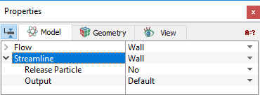
The treatment of streamlines at a boundary is specified in three ways: Open, Wall and Symmetry.

Figure 5.249 - Particle
Open
|
The open boundary condition allows the streamline to enter/exit the domain. An Open boundary typically corresponds to a Flow module Inlet or Outlet, but can apply to other type Flow boundary as well. |
Wall
|
The wall boundary condition for the Streamline module typically corresponds to a Wall boundary in the Flow module. |
Figure 5.251 - Wall boundary conditions |

Symmetry
|
The symmetry boundary condition for the Streamline module causes the streamlines to reflect at the boundary. This corresponds to a Symmetry boundary in the Flow module.
|
Figure 5.252 - Symmetry boundary conditions |
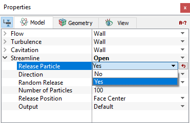
Streamlines can be released at an open, wall or symmetry boundary by setting Release Particle to Yes.
Release Particle
Release Particle activates the release of streamlines at a boundary. To activate the release of streamlines, Click Yes for Release Particle option. The Release Particle option is also available for a Streamline module interface, if the interface is between a solid and fluid volume. With the activation of Release Particle, the following parameters/variables are defined to serve as the initial conditions for the streamline:
- Direction
- Random Release
- Number of Particles
- Release Position
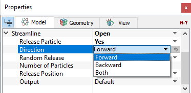
Direction
|
There are three options for tracing the direction of a streamline released at a boundary. They are:
|
Figure 5.253 - Direction |
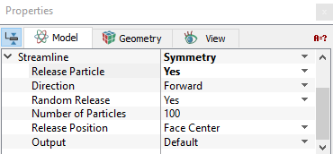
Random Release
At a boundary, streamlines can be released randomly. When Random Release is set to No, Simerics-MP automatically allows the streamlines to be released from each boundary cell center, face center or both the face and cell center depending on the choice of Release Position.
Number of Particles
When Random Release is set to Yes, the number of streamlines released from the selected boundary is required to be specified.
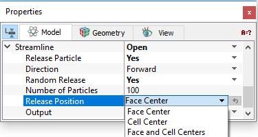
Release PositionFor each streamline, the starting or release position
|
Figure 5.254 - Release position |
 is specified when it is released. At a boundary, the release position can be determined by one of the three options:
 .
. .
.
Interface Conditions
The Interface attributes for the Streamline module are the same as for the boundary conditions, if and only if one side of the interface has been Blanked for flow, i.e. it is a solid wall. If, instead, the Flow module is Active on both sides of an interface, then the interface is treated as a default interface and cannot be assigned any special attributes.